A saved program is only part of a successful bending job. The material, installed tooling, gauging strategy and inspection record also have to agree. This guide helps buyers and trained operators understand that relationship before they stand in front of an ESA S840 W.
Know what your S840 W actually includes.
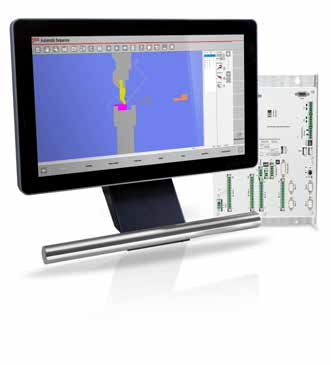
S840 W is the standard BENDRYX control platform. ESA’s 2024 bending brochure lists a 15.6-inch, 1366 × 768 display and graphical 2D workpiece and tool preparation. It lists four axes, with six as an option. The 2D optimizer is optional; a 3D optimizer is not listed for this model. S840 W Lite is a different product.
Ask for the installed axis list and software options on your quotation. A display showing a 3D example elsewhere in the ESA portfolio does not establish that your controller has that function. See the S840 W specifications and the controller comparison.
Workflow illustration: BENDRYX. This is a planning sequence, not a reproduction of the CNC screen.
Build a job record before building the program.
Start with a controlled drawing revision. Decide which dimensions are critical, how they will be measured and whether the drawing specifies an inside or outside dimension. A perfectly repeated program can still produce the wrong part if the starting assumptions are wrong.
| Record | Why it matters |
|---|---|
| Material grade and measured thickness | Do not rely only on the nominal sheet description when evaluating bend results. |
| Drawing revision and tolerances | Keep the program tied to the approved part definition. |
| Punch, die and clamping identifiers | The selected library entries must match the physical tools and approved installation. |
| Tool and machine load limits | Have the proposed process checked against the limits of the complete setup. |
| Finish, grain and handling requirements | Plan how to protect the part and support it throughout the sequence. |
A useful naming convention is part number · revision · material · thickness. Include the machine and setup revision in the accompanying record, especially when several press brakes share a program library.
Think about the whole part, not isolated angles.
Each bend changes the shape that must be loaded, supported and located for the following bend. Before release, review whether formed flanges obstruct the tooling, whether a stable gauging surface remains and whether the operator can handle the part using the approved support arrangement.
What the axis names tell you
On an appropriately equipped machine, X describes backgauge depth, R describes gauge height and Z1/Z2 describe lateral finger positioning. Y1/Y2 are ram axes, not backgauge axes. The letters explain motion functions; they do not prove which channels your machine has. Explore backgauge layouts.
Separate planning software from onboard capability
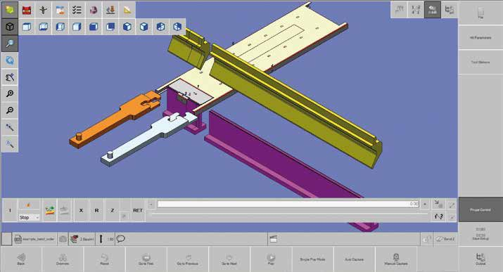
ESA’s EsaBend 3D-M illustrations show offline tooling, sequence and clearance planning. That is a separate software workflow to confirm with the machine postprocessor and license—not evidence of onboard 3D programming on S840 W.
Release a measured part, not just a completed cycle.
The first part is a process check. Use your approved setup and verification procedure, then inspect the required angles, flange dimensions and overall geometry against the drawing. Record what was measured before deciding what needs correction.
- If an angle is wrong, check the material and tool identification before applying a correction.
- If a flange dimension is wrong, review the dimension convention, blank and gauging method.
- If results vary across the bend, stop and have the setup assessed rather than hiding the variation with unrelated offsets.
- If the result changes between parts, investigate repeatability and material variation before releasing a batch.
Keep correction changes traceable. Record the reason, the measured result and the approved revision so another operator can understand the setup rather than guessing which offset was intentional.
Preserve the setup that produced the approved part.
Save more than the program name. A repeatable handover includes tool station positions, material identification, accepted measurements and any approved correction history. Keep a released version separate from a working copy so experimentation does not silently overwrite a proven job.
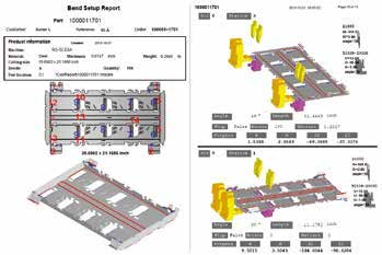
Use the export or backup method documented for your installed system. Confirm the destination and file selection, retain a dated copy under your company’s access controls and verify that it can be recovered using the supported process. Program backups and complete machine-configuration backups are not interchangeable.
Do not import another press brake’s protected settings or assume its programs are interchangeable. A different rack, tool library, axis arrangement or machine geometry can change what a file means.
Questions to ask before your first job
Does standard S840 W mean every ESA feature is included?
No. Check the quotation for the actual axes, licenses, interfaces and accessories. Portfolio features are not a list of installed equipment.
Can I follow any online S840 video button for button?
Not reliably. Confirm the control variant, software version and machine configuration first. Use your supplied manual for exact screen navigation and operating instructions.
What should I send when requesting help?
Send the machine model and serial number, control/software version, program revision, alarm text if present, and a clear description of the expected versus measured result. Do not continue running an unsafe or unexplained condition.
Turn the lesson into a specification
Choose a control package around your work.
Share a representative part, your gauging requirements and whether you want programming at the machine or in the office. BENDRYX can help define the control package and training questions for your application.
Configure with ESA S840 W →Product specifications and manufacturer illustrations: ESA VIS-600/800 bending brochure, printed pages 12–21 and 28–31. Additional product reference: ESA VIS-800 family. General workflow recommendations are BENDRYX educational guidance, not a substitute for the machine-specific manual.