Start from the supplier drawing
Collect the tool identifier, dimensions, profile and rated load. Default templates are starting shapes, not verified specifications. Values displayed in the examples must not be reused as production settings.
Use the reference screens below alongside this explanation. Select an image to inspect its original size.
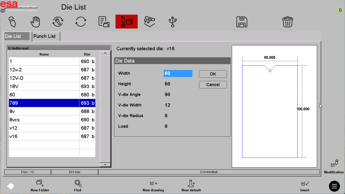
Create and verify the record
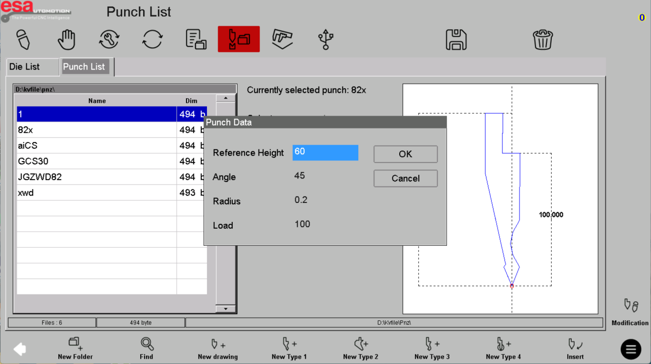
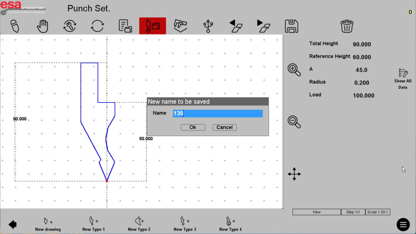
The die and punch screens provide geometry fields and a profile preview. Complete the applicable dimensions from the tool documentation and save a distinctive name. Check that the displayed profile corresponds to the actual tool and clamping interface.
Use the reference screens below alongside this explanation. Select an image to inspect its original size.
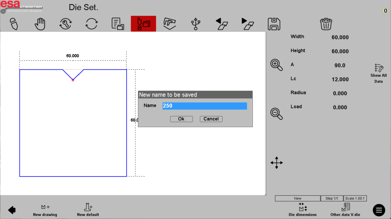
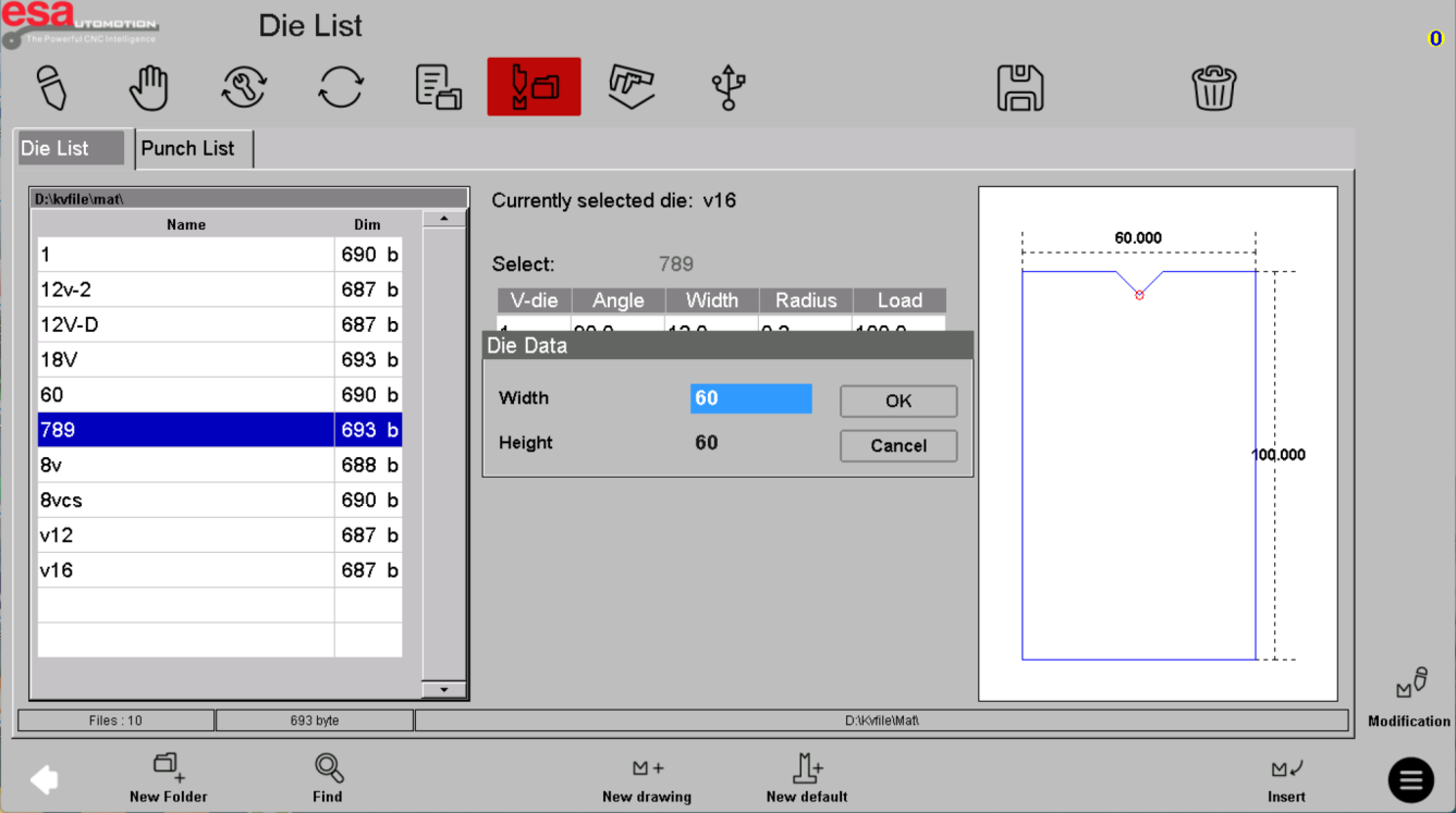
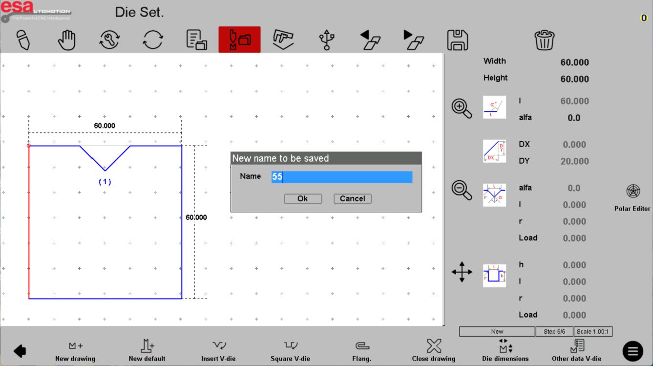
Control later edits
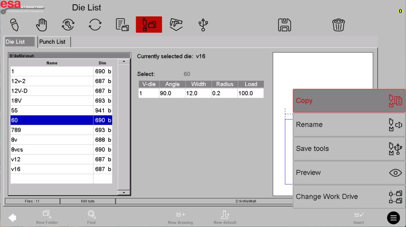
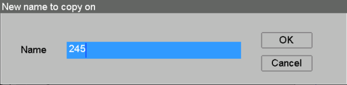
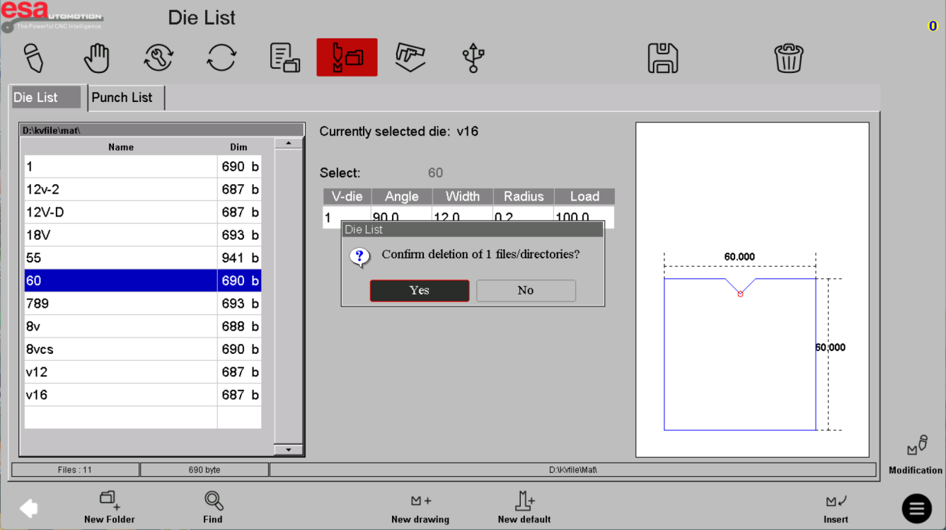
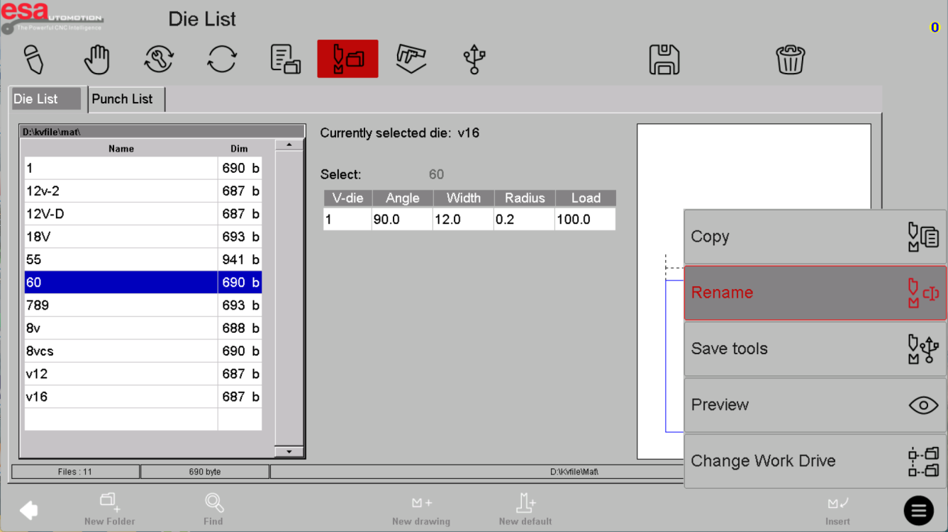
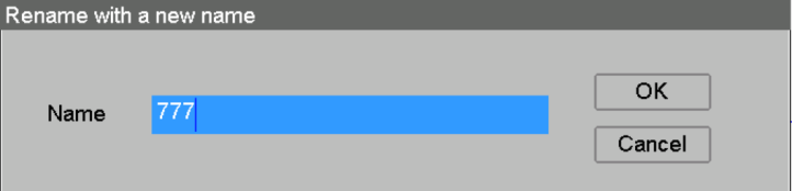
Prefer a clearly named revision when changing geometry used by released programs. Copy, rename and delete operations affect the library, so check dependent jobs before cleanup. Have the completed setup reviewed under your company's tooling procedure.
Use the reference screens below alongside this explanation. Select an image to inspect its original size.
Before using this on your machine
- Confirm S840 versus S840 W and the installed software revision.
- Check that the documented functions match your licenses and fitted axes.
- Protect released program and tool-library versions before changes.
- Use qualified support for motion, reference, force and safety-related settings.
S840 W specifications and option notes →
Discuss your control requirements →BENDRYX educational commentary with permission-based S840 reference screenshots. This lesson is not a machine certification, a commissioning instruction or a replacement for the supplied operating manual.