The force path
The servo motor drives the screw assembly, converting rotary motion into controlled linear movement. Bearings and clamping interfaces carry the mechanical loads.
ESA bending systems · Brochure guide
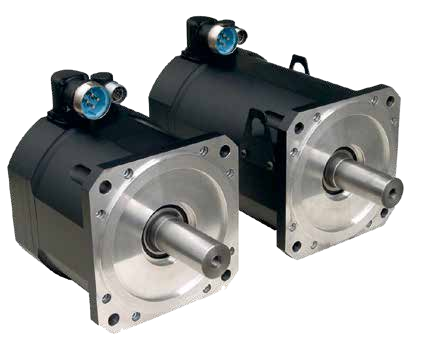
An electric press brake uses a motor-driven mechanical transmission rather than a hydraulic forming circuit. The ESA brochure illustrates matched motor, screw, bearing and drive assemblies.
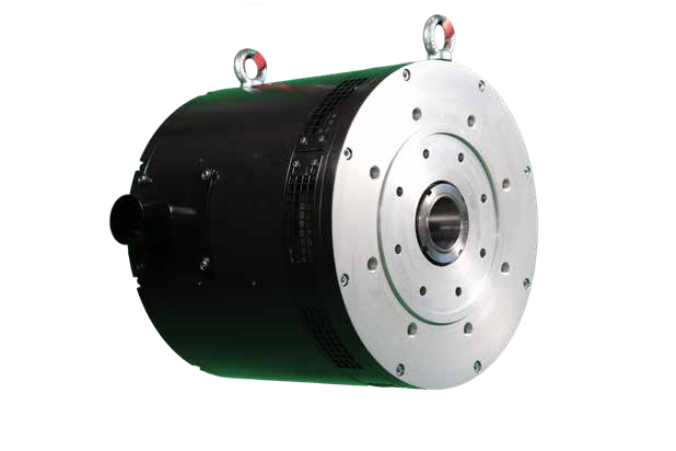
The servo motor drives the screw assembly, converting rotary motion into controlled linear movement. Bearings and clamping interfaces carry the mechanical loads.
Motor torque, screw dimensions, bearings, braking and cooling must match the machine. Changing the CNC alone does not change press-brake tonnage.
Use the electric machine’s own technical sheet for force, travel and speed. These ESA component illustrations explain the architecture and are not a BENDRYX bill of materials.
Open an illustration at its original extracted size. These are manufacturer reference images, not photographs of a specific BENDRYX installation.
Explore ESA controllers → · Continue to offline programming →
ESA manufacturer reference, not a guarantee of the equipment installed on any individual BENDRYX machine. The quotation determines rack, axis count, software licenses and accessories. ESA S840 W is our standard platform; other models and systems require application and availability confirmation.
Images and specification reference: ESA VIS-600/800 bending brochure (2024), printed pages 40–47. Manufacturer illustrations retain their original appearance. Published brochure values should be reconfirmed against the current supplied configuration.
Tell us your machine, parts, gauging and programming requirements. We will confirm the control and options in your quotation.